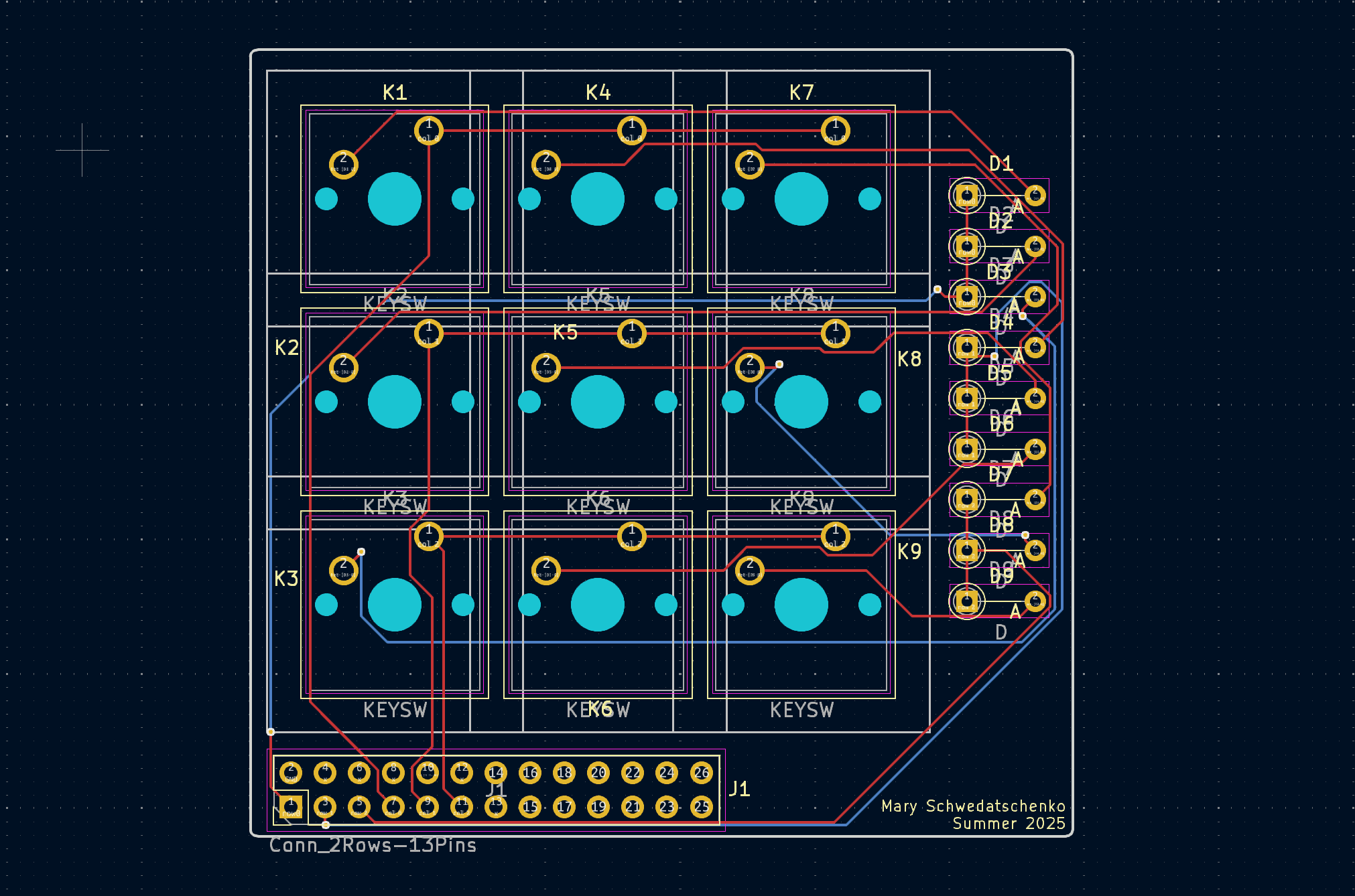
custom macropad pcb
2025
summary
Custom 3×3 mechanical macropad designed as a full schematic-to-firmware exercise: PCB layout in KiCad, board fabrication, and USB HID firmware on an Arduino Micro.
hardware
- Nine mechanical switches arranged in a 3×3 matrix, reducing I/O requirements to six microcontroller pins (three rows and three columns).
- One diode per switch blocks reverse current paths that cause ghosting, enabling reliable multi-key presses without phantom detections.
- Schematic, custom footprints, board outline, and hand routing completed in KiCad prior to fabrication.
- Board geometry includes an angled outline chosen during layout rather than left as a default rectangle.
firmware
- Firmware runs on an Arduino Micro and enumerates to the host as a standard USB HID keyboard, requiring no custom drivers.
- Scan loop drives one row at a time, reads column states, applies software debouncing, and reports key events over HID.
- Matrix scanning and debounce timing were tuned for reliable single- and multi-key input under normal typing cadence.
process
- Project scoped as the smallest board that still exercises the full PCB workflow: schematic capture, footprints, routing, fabrication, assembly, and firmware bring-up.
- Hand routing the matrix highlighted the gap between a correct schematic and a practically routable board layout.
- built with
- kicad, c++, arduino micro, usb hid